
Relying on the internet for time seems a little silly to me when we have high-tech objects speeding past over-head giving us an incredibly accurate, non-connected time source, most folks call it GPS.
Update: Feb 12 2022 Thanks to Rob Thomas [Linked In↗] who had been working on some GPS issues he was experiencing at the same time I was working on this project. You can find his ansible build scripts for setting this all up on his github at https://github.com/xrobau/rpi-ntp↗ upon which work this article was greatly enhanced!
| Project Cost | Build Time | Assumed Knowledge |
|---|---|---|
| $10-$60 | 4hrs | Basic Linux Familiarity with Single Board Computers (eg Raspberry Pi) |
| Minimum Electronics Knowledge (GPIO Use) |
Background
But isn’t GPS about location?
GPS is a system of 30+ navigation satellites circling Earth. A GPS receiver in your phone or other device listens for these signals. Using the time it takes signals to travel at the speed of light from the satellite to the receiver a location can be triangulated, often using 8 or more of the satellites available. In order to do this GPS satellites utilise multiple onboard atomic clocks - as clocks must be accurately synchronised in order to calculate the distances accurately.
Even these small atomic clocks on GPS can drift over time and an update is sent to each of them twice a day to keep their time in sync with larger, more accurate, earth-based atomic clocks, that could not survive the journey to space.
GPS broadcasts it’s signals using two frequencies known as L1 at 1575.42Mhz and L2 at 1227.6Mhz with timing signals and binary data known as alamanac and ephemeris. Spread spectrum signals are handled by using unique frequency hopping coding, uniquely idenitfying each satellite.
If you’d like to deep-dive into the nitty-gritty technical details on how the Global Positioning System network works, the Australian Institute of Measurement’s Dr Bruce Warrington produced an excellent slide deck available in PDF from Engineers Australia entitled GPS and Time: Using Clocks in Space for Accurate Time on the Ground 📄↗
The term stratum means the same here as it does geologically, “a layer or a series of layers of rock in the ground.”, though we’re talking about layers of accuracy in a time source, a clock receiving it’s time from a stratum 4 source is in itself a stratum 5 clock. The GPS clock in our configuration here is a Stratum 0 clock providing it’s time to a Stratum 1 time server.
Hardware
GPS Modules
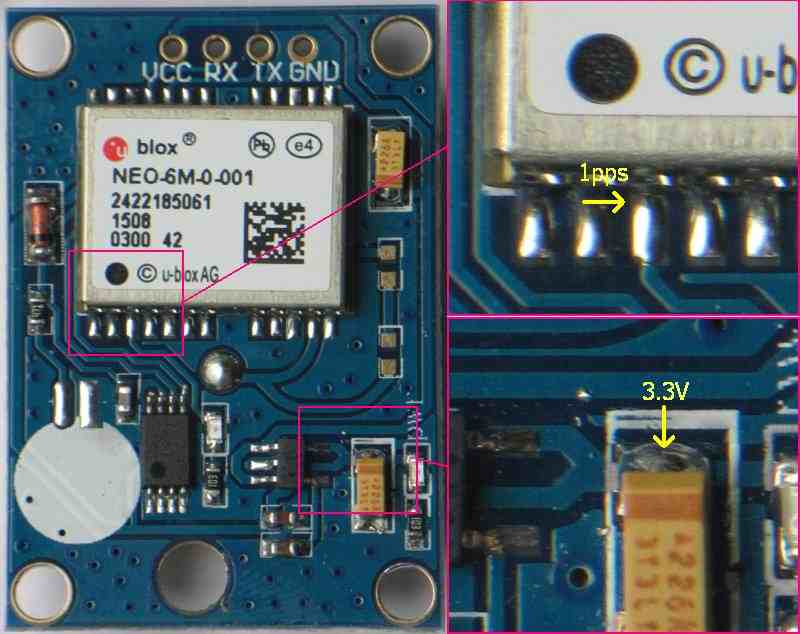
Just about all GPS modules available utilise TTL-level UART (Serial) connectivity to deliver their data to a host. If you want accurate time keeping you also want a PPS (Pulse-Per-Second) signal from the module, allowing the host to perform an interrupt on this line and keep the clock in sync every second.
All my early tests were conducted with a cheap GPS reciever designed for drones; though it appears many on the market are based on this chipset.
You can get PPS from one of these modules if you’re really keen, see below for more details.
If you’d prefer a pre-built waterproof enclosure that includes the PPS line, you could consider an item more like this USB-based device, which has the benefit of not requiring any GPIO connectivity or soldering.
Computer - As the Planespotting project is in production in the bedroom window with access for external small receiver antennas, the ADS-B project was selected to host the GPS clock after testing was done with the Balcony Test rig. The ARM Core processor in this Orange Pi is more than capable of providing multiple services:
ADS-B Reciever - Orange Pi based PlaneSpotting
Getting PPS from a Module without it
On the Neo modules without PPS broken out, you can do it yourself if you’re keen:
This image and more info can be found at Alan Cashin’s A Low Cost Sidereal Clock↗ page. Used with permission.
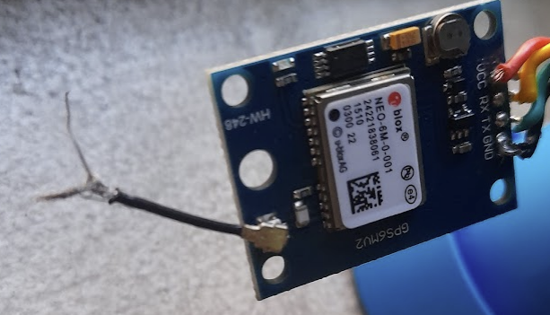
Tread Carefully
Be careful with the connectors and antenna for the Neo modules; on day 1 of experimenting I borked mine pretty badly; it took much time and effort to split and solder the tiny connector cable bac inside the antenna, it was midly successful for the remainder of early testing until a replacement unit arrived a week later.
Getting Wired Up
Skip this section if you’re using a USB module.
If you’re going with the Neo module; you’ll need to get your TTL UART TX/RX lines and VCC/GND connected up to a suitable serial port. On the Orange Pi I already had in production the most convenient pins for this were UART2 as they are handy to 3V3 and GND lines on the GPIO header pins.
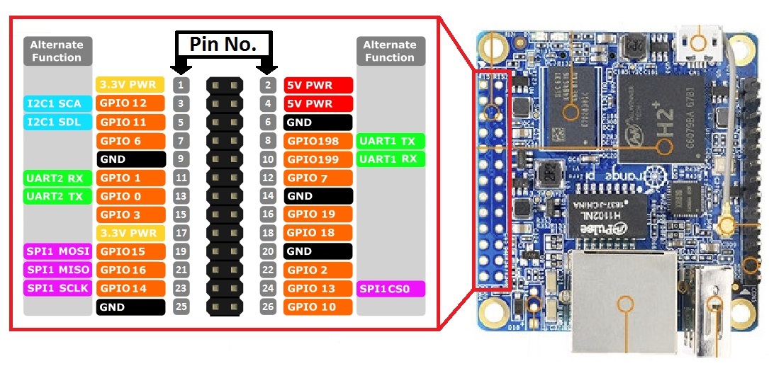
We connect the RX line from the Neo module to the TX line of the Orange Pi and the TX line to the Orange Pi’s RX line. As usual, VCC to 3V3 and GND to GND. I soldered and heatshrank female DuPont headers to the lines to make them easy to connect and disconnect from my various Orange Pi setups. GPIO6 (PA6 in Oranage Pi speak) makes a good candidate for the PPS interrupt line, especially if you’re using DuPont headers as I find that they hold better when neighbouring pins are also occupied. The usual advice of if it’s semi-permanent just solder it, always applies!
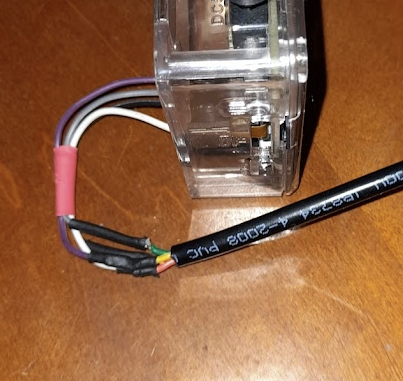
This is my original test wiring, before using a PPS line for more accurate time keeping. Note the use of heatshrinking - solder of course under it, but I love heatshrink.
The Module defaults to 9600 baud serial, 8 bits, No Parity, 1 stop bit. There are no CTS/RTS connections required.
Of course if you opted for the USB model you can skip this wiring step and plug in the USB cable!
The Software
Installing the Software
At bare minimum for a production system you’ll want the universal GPS daemon - gpsd and the related client tools found in the debian gpsd-clients package. For debugging purposes you may also want miniterm found in the pyserial/python-serial package. A modern network time server is essential if you want to share the time from your new GPS clock to the rest of your network, I recommend ntpsec, a secure, hardened, and improved implementation of Network Time Protocol derived from NTP Classic, Dave Mills’s original.
I’m a python dev primarilly so I added the python libraries for GPS too to have a play with in future.
Let’s get the entire collection of suggested tools installed, inluding a couple of dependencies:
1
2
apt update
apt install miniterm pyserial python3-serial python3-gps python-gps gpsd gpsd-clients ntpsec
Boot Environment
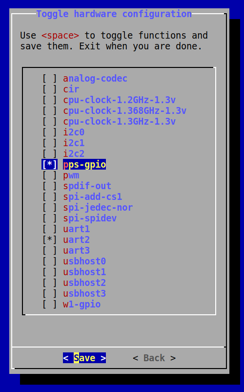
You can use the armbian-config command to setup UART2 (which appears as /dev/ttyS2) and the gpio-pps kernel modules; you can do this on the command line if you wish, but runnig armbian-config, selecting System and Hardware is the easiest option.
Even if you do it this way, you should ensure the contents of your /boot/armbianEnv.txt are correct; or if you’d prefer to just edit yourself and not dealing with the whiptail menu system that armbian-config provides, here’s the bits you need:
1
2
3
overlays=uart2 pps-gpio
param_pps_pin=PA6
extraargs=nohz=off
Serial Optimisations
1
2
3
setserial /dev/ttyS2 low_latency
/usr/bin/stty -F /dev/ttyS2 -echo
Reboot
To be safe, I like to run a update-initramfs -u to update the boot kernel and parameters and reboot after making these changes, before moving on to making sure everything is working.
Check your PPS
You can test your PPS device using, funilly enough, ppstest /dev/pps0:
1
2
3
4
5
6
trying PPS source "/dev/pps0"
found PPS source "/dev/pps0"
ok, found 1 source(s), now start fetching data...
source 0 - assert 1644669667.999939933, sequence: 389110 - clear  0.000000000, sequence: 0
source 0 - assert 1644669668.999946406, sequence: 389111 - clear  0.000000000, sequence: 0
source 0 - assert 1644669669.999950202, sequence: 389112 - clear  0.000000000, sequence: 0
Check your GPS
You can test the GPS device using the gpscat /dev/ttyS2 command:
1
2
3
4
5
6
7
8
9
10
11
$GNRMC,130840.00,A,3353.27213,S,15111.85287,E,0.025,,120222,,,D*78
$GNVTG,,T,,M,0.025,N,0.046,K,D*3D
$GNGGA,130840.00,3353.27213,S,15111.85287,E,2,11,0.77,30.2,M,19.2,M,,0000*6F
$GNGSA,A,3,04,09,07,20,27,30,08,14,,,,,1.53,0.77,1.32*18
$GNGSA,A,3,70,74,71,,,,,,,,,,1.53,0.77,1.32*19
$GPGSV,3,1,10,04,24,040,22,05,10,227,,07,64,172,19,08,40,102,20*7B
$GPGSV,3,2,10,09,61,029,36,14,38,307,25,20,18,255,26,27,20,132,26*7A
$GPGSV,3,3,10,30,51,226,34,50,43,321,31*7E
$GLGSV,3,1,09,70,25,004,13,71,66,310,33,72,40,222,23,73,51,171,19*61
$GLGSV,3,2,09,74,44,253,20,75,02,287,,80,16,130,,82,12,134,*67
$GLGSV,3,3,09,83,15,089,*52
Configuring GPSd
I found just letting gpsd do it’s own thing with minimal instruction tends to work best, so edit the /etc/default/gpsd configuration file with your preferred text editor and update it to reflect your serial port device and -n which makes gpsd start using the device immediately rather than waiting in a low-power standby mode until it’s needed:
1
2
DEVICES="/dev/pps0 /dev/ttyS2"
GPSD_OPTIONS="-n"
The -n flag for GPSD_OPTIONS tell GPSd not to wait for any clients to connect before processing GPS packets.
Additionally I specify -G to listen on all network ports as that allows any device on my network to utilise the GPS server. I additionally found issues with my particular GPS unit and the Orange Pi UART if I did not lock the baud rate to 9600 baud. My GPSD_OPTIONS value is -G -n -s 9600.
GPSd also has a magic “/dev/gpsd0” device that can be used which automagically adds the PPS device and presents them as two separate devices, there are some further issues to investigate with this approach. I find the more reliable way is to ensure gpsd has both devices specified.
1
2
systemctl enable gpsd
systemctl start gpsd
Now, ensure your antenna is connected to the module and has a good clear view of the sky without obstructions that will interfere with signals at the 1 gigahertz range that GPS operates in; and run gpsmon to see what your GPS is doing!
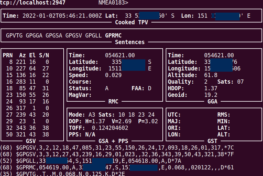
If all goes well you’ll see a count of the satellites connected and the current time and location (mine is redacted of course). The output of gpsmon may differ depending on the protocol being used with your GPS receiver, but all modes will result in an accurate time, location and quality indication (number of satellites used). If you’d like to do a deep-dive into the actual protocol used to exchange data between the module and host you can take a look at the NMEA 183 standard ↗.
Configuring NTP for Network Time
Having been a sysadm since the late 90s; I’m reluctant to look at the ‘modern’ NTP replacements like chrony, but I hear good things about them. The original ntpd by Dave Mills has been around forever and has some security issues, but a team of amazing volunteers has taken on this project and produced ntpsec, I highly recommend this option, so that’s the one detailed here.
We can ignore the /etc/default/ntpsec file in this case; as it’s just sensible defaults; instead we’ll take a look at /etc/ntpsec/ntp.conf, and the lines specifically for adding a shared memory or virtual network clock, these psuedo addresses are used for different types of clocks with 127.127.1.0 reserved for your local systemclock (not something that you should use); here’s some of the virtual network clocks defined by the NTP standard:
- Type 1 Undisciplined Local Clock (LOCAL)
- Type 8 Generic Reference Driver (PARSE)
- Type 17 Datum Precision Time System (GPS_DATUM)
- Type 20 Generic NMEA GPS Receiver (NMEA)
- Type 22 PPS Clock Discipline (PPS)
- Type 28 Shared Memory Driver (SHM)
- Type 30 Motorola UT Oncore GPS GPS_ONCORE)
- Type 33 Dumb Clock (DUMBCLOCK)
- Type 36 Radio WWV/H Audio Demodulator/Decoder (WWV)
- Type 46 GPSD NG client protoco
As our gps server and ntp server run on the same network we’re going to use the shared memory (28) driver, so add these two lines to the configuration:
1
2
3
4
…
refclock pps unit 0 refid PPS minpoll 0 maxpoll 4 stratum 15 flag2 0 flag3 1 flag4 1
refclock shm unit 0 refid GPS minpoll 0 maxpoll 4 stratum 15 prefer
…
Ensure that ntpsec is enabled and start it off to test the GPS shared memory clock.
1
2
systemctl enable ntpsec
systemctl start ntpsec
For now the important thing to remember is to force this as a low-stratum clock (15) while we’re testing as to not affect our current network time until we’re ready to do so. We give it a reference ID (GPS) and an offset, that offset we will adjust soon.
There’s other settings in this file you may want to look at like including some internet time sources as well; and armbian by default will use the public ubuntu pool of time servers.
Did it work?
Like gpsd, our time server has a tool which can be used to see how it’s performing; that tool is ntpq (network time protocol query), so we run the command ntpq -c peers on our sOrange Pi:
1
2
3
4
5
6
7
8
9
10
11
12
13
14
     remote                                   refid      st t when poll reach   delay   offset   jitter
=======================================================================================================
 PPS(0)                                  .PPS.           15 l    6   16  377   0.0000 -114.300   0.0300
 SHM(0)                                  .GPS.           15 l    6   16  377   0.0000 -116.439   2.0221
*catsl################.org               139.99.222.72    3 u   11   32  377   0.3650  -0.0437   0.1351
 serenity.catslair                       .DNS.           16 u    -   32    0   0.0000   0.0000   0.0010
 time.cloudflare.com                     .NTS.           16 7    -  512    0   0.0000   0.0000   0.0010
 au.pool.ntp.org                         .POOL.          16 p    - 1024    0   0.0000   0.0000   0.0010
-y.ns.gin.ntt.net                        204.2.140.74     2 u  618 1024    1  14.0685   2.3213   0.1256
+time.cloudflare.com                     10.26.9.65       3 u  618 1024    1  14.0051   1.3210   0.1326
+ntp3.ds.network                         218.100.43.70    2 u  618 1024    1  62.0535  -0.5893   0.1282
-pauseq4vntp2.datamossa.io               203.35.83.242    2 u  362 1024    1  15.3318   1.7495   0.4183
-dns01.ntl02.privatecloudco.com          110.142.180.39   2 u  362 1024    1  19.8433  -0.8128   0.2023
+ntp2.ds.network                         162.159.200.123  4 u  362 1024    1  62.9446  -0.4334   0.2466
NTP is usually very good at picking the best time sources; and reading the output above the first thing to notice is that SHM(0) (GPS) has a stratum 15 value - which is great, I don’t want it being authoritive in anyway until we’re sure of it’s accuracy.
The offset is a concern, but we’ll keep an eye on this over a day or so to see how it goes.
Graphs and Fudge!
If you’d like great data and graphing of NTP you can install ntpsec-ntpviz, for an example of the output from these tools take a look at
otherwise you can regularly monitor it with human eyeballs and the ntpq command, and adding the -u option to ntpq will print the SI units similiar to the way du does with it’s -h option for human readable.
If you need to fudge your clock a little you can using the time1 paramter.
1
refclock shm unit 0 refid GPS minpoll 0 maxpoll 4 time1 0.1315 stratum 3 prefer
Play with the time1 value on the fudge line to adjust the offset to bring it inline with a low-stratum network time source. I found the value of .1229 worked well for me (and is close to the 116 milliseconds reported by peers initially.
Once you’re happy with it drop the stratum of your GPS clock down, I use Rob’s recommended value of 3.
1
2
refclock pps unit 0 refid PPS minpoll 0 maxpoll 4 flag2 0 flag3 1 flag4 1
refclock shm unit 0 refid GPS minpoll 0 maxpoll 4 stratum 3 prefer
Leaving NTP running for a little while (15 minutes or so), we come back to check on it again:
1
2
3
4
     remote                                   refid      st t when poll reach   delay   offset   jitter
=======================================================================================================
oPPS(0)                                  .PPS.            0 l    -   16  377      0ns 12.764us  2.443us
*SHM(0)                                  .GPS.            3 l   46   16  374      0ns -4.705us 17.343us
That’s pretty damn good if you ask me. No time1 fudging need yet, we’ll come back and check on it in another day.