
Introduction
If you’re not familiar with Flight Tracking and ADS-B in general, you should start at Planespotting - My ADSB Setup for how my station was built and where you can find the data I export from it, both to public hubs and a real time live view of just my station (though I encourage friends and folks to send data there, get in touch if you’d like to!)
The Original Antenna
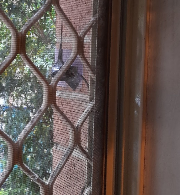
For the original ADS-B station I built I trimmed the RTL-SDR provided whip antenna down to an exact 1/4 Wavelength for 1090Mhz ADS-B:
Thanks to ADS-B being such a short wavelength (275mm), a half wave dipole design should perform better than the whip that had been in use, and inspired by several antenna makers on YouTube I decided to try a really simple approach, fold back the shielding on coax, make it the ground and use the coax inner conductor for the active element.
Getting Started
First we need to know how long each leg of our dipole should be, you can do the math yourself or any of the handy dipole calculators for this.
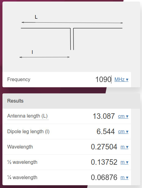
You can use this calculator and read about the formulas used at OmniCalculator - Dipole↗.
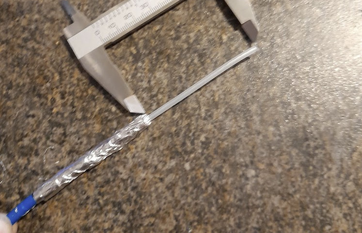
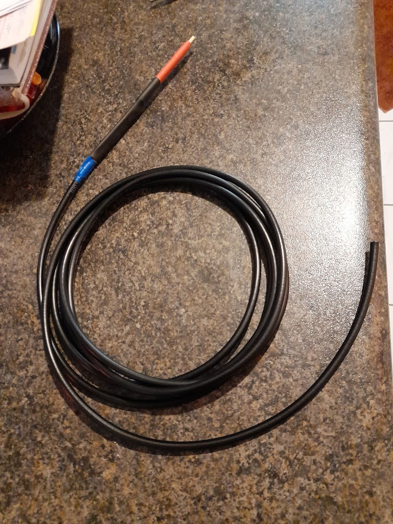
Next we trim back the insulation and shielding on the coax - ensuring you’ve got enough to make the quarter wave, as this is an RX antenna the closer you get to the right length the better. Try to get the insulation off in one section if you can, it comes in handy later!
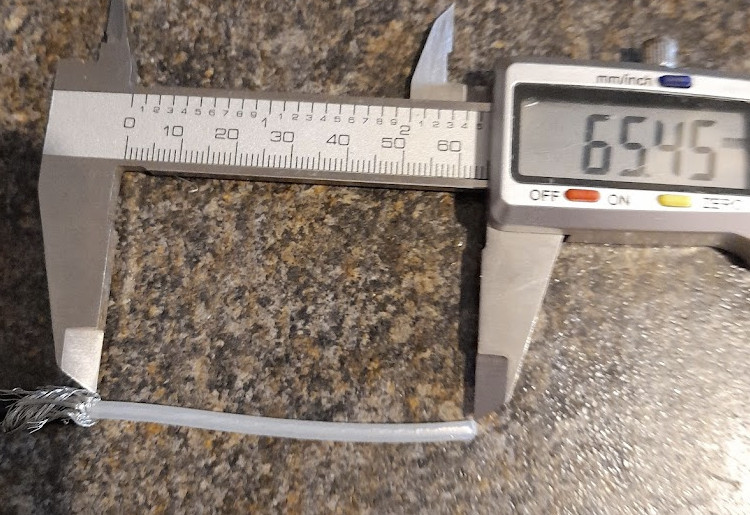
Measure the same distance for the other “leg” of the dipole (the shield side) and I place a strip of tape at that point on the insulation to make it easier to work with without constantly measuring it. Fold back the shielding; trying to retain as much of it as possible and stretch down the insulation as far towards the tape line you can.
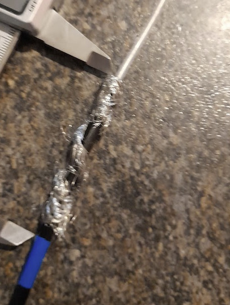
Next I take a thin strip of aluminium foil and add this ontop of the cable shielding to form a much better conductor.
To keep the foil securely in place and ensure it remains so, some heatshrink is used.
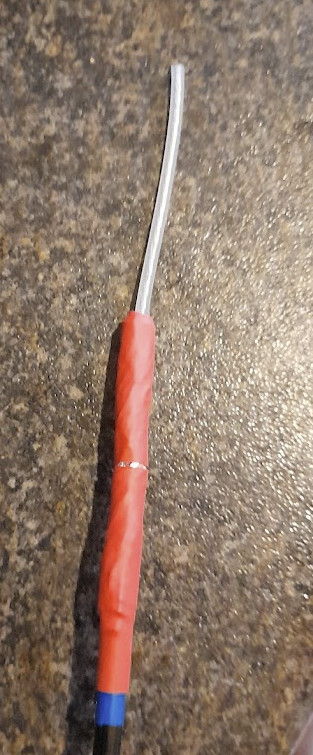
The coax I’m using was an offcut from a new feedline I ran on my balcony, and it’s not the most rigid of cables, so we add some mechanical support to the antenna section, mostly to keep it as straight as possible. Using a BBQ Skewer from the kitchen drawer and re-using the insulation that was stripped from the very first step of this project, I construct a reasonably solid support and temporarily hold it in place with some electrical tape.
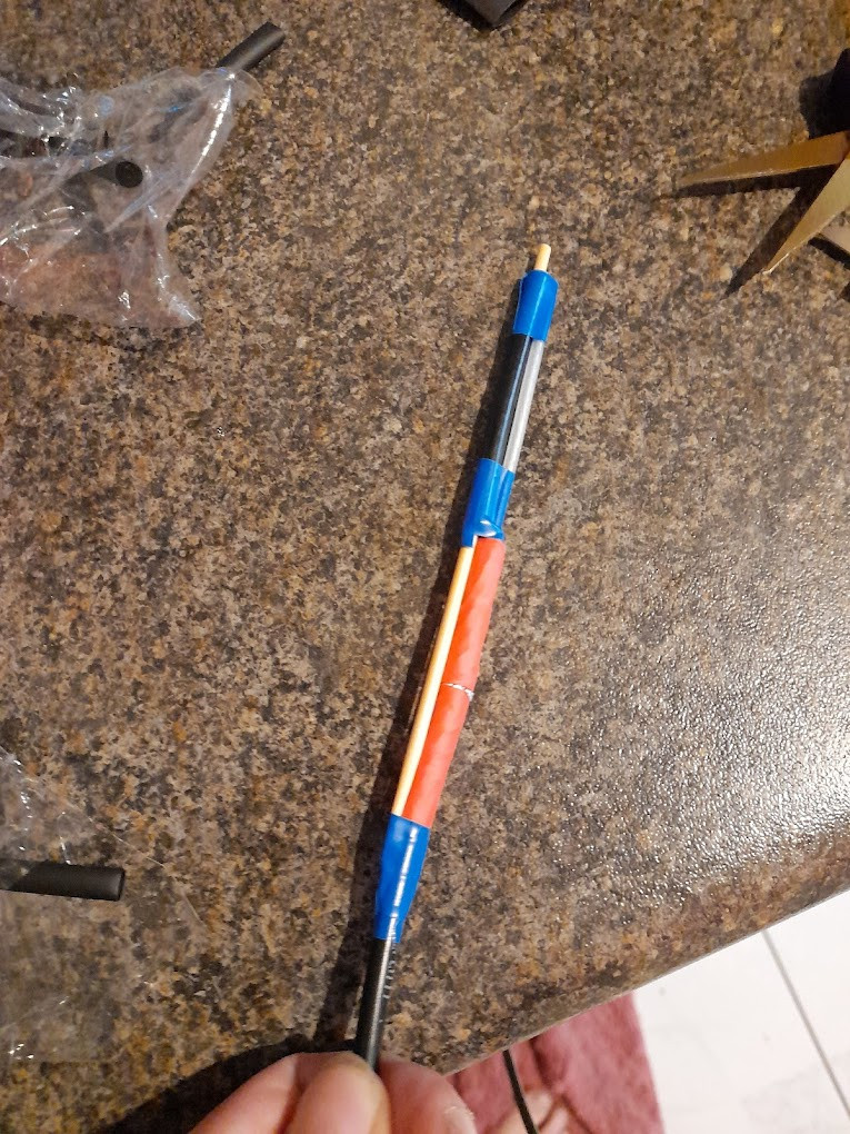
Next we secure everything with heatshrink again. In my test version of this antenna I just used tape and wrapped it tightly, but heatshrink is a much better solution for a more solid final product.
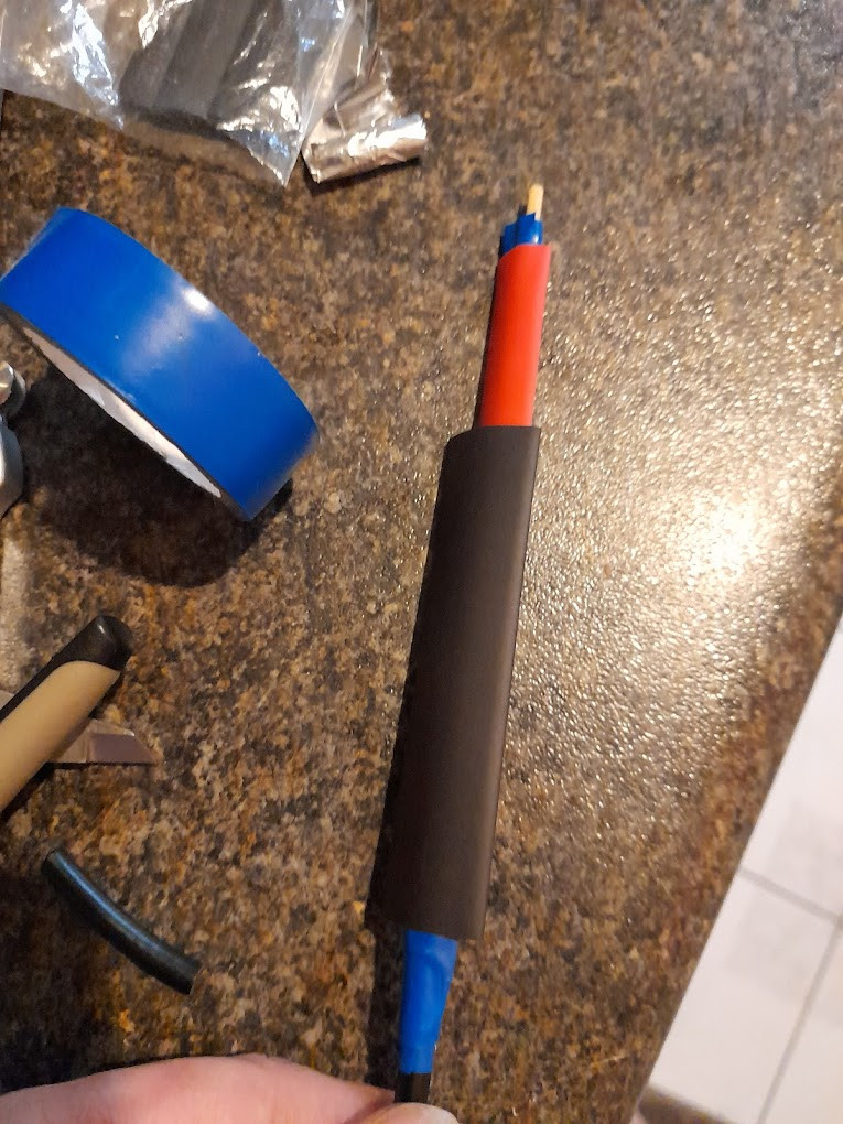
Once the heatshrink is shrunk and everything is in place and solid, you should have something that looks like this:
All that’s left to do is add the appropriate connector for your radio, in my case an SMA connector, you can find plenty of guides online for how to crimp connectors so I won’t cover the graphic details here - and it’s one of my least favourite things to do!
Here’s a video tutorial for you if you’re not sure though: YouTube: SMA Crimp Connector Installation↗.
How does it perform?
… Standby for test results. Unfortunately I cannot compare it to the original antenna as the first version of this build (a very rough one) has been in production for several weeks and while it performs well, the plan is to replace that with this one in the next day.
For comparison to the rough version of the antenna, it currently reaches about 40 nautical miles from my ground floor apartment in the city - not too shabby! I’ll add graphs to this post in about a week once enough data is collected to be sure it performs at least as well.