
Starting from a coffee table next to my balcony and an RG58 cable running out to the antenna, this project takes that network Software Defined Radio Receiver and puts it on the balcony providing the centralised hub for an entire eco-system of balcony radio and sensors.
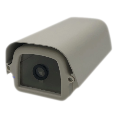
There was never meant to be a camera on this project, though I had always wanted to put one on the balcony, this was becoming more important as antennas were being mounted, but when a great weatherproof security camera enclosure was spotted on AliExpress the project started to take a different form:
Desired Features
- Radio Receiver (one or two)
- Network Security Camera
- Ethernet / PoE
- Integration with the Weather Station Project via UART
Ideally I’m hoping to run dual receivers on this setup but this will largely depend upon power consumption and space in the final build.
Optional Features
- Battery Backup
- Solar Monitoring
Parts List
Many of these parts decisions were made because of things I already had here, some alternatives are suggested, but as usual my projects are designed to motivate you to find interesting things to do and demonstrate how it can be done, not to give a detailed how-to. Feel free to contact me if you’d like help doing something similar!
Prices in approx. Australian Dollars at the time of purchase.
PC/Compute
- Orange Pi One 🛒 or the Official Shenzen Xunlong Store↗ on AliExpress ($40).
- Weatherproof Camera Enclosure↗ ($30)
- 12V Power Over Ethernet Passive POE↗ ($6)
Radio
- Nooelec NESDR SMArTee XTR SDR 🛒 ($50)
- Nooelec LNA 🛒 ($30)
Camera
- OVC2640 2MP CSI Camera 🛒 ($2)
All my testing was performed using the Nooelec NESDR SMArt v4 Software Defined Radio 🛒 dongle, so that may be pictured in many of my pictures, however due to the need to mount the LNA inside the PVC pipe the XTR version will eventually be used. If powering the LNA using USB and not the bias-T input you should place a Nooelec DC-Block 🛒 between the SDR and LNA.
Hardware yet to arrive
- GPS Receiver
- Infrared Lighting
Cabling
- Ethernet Connectivity (reduce RF noise on my balcony)
- PoE to minimise cabling to balcony
- Coax to Antenna
Orange Pi Pinout
SunXi boards use a different naming system to most others, the board can be powered using 5V connected to either of the 5V marked pins (2 and 4).
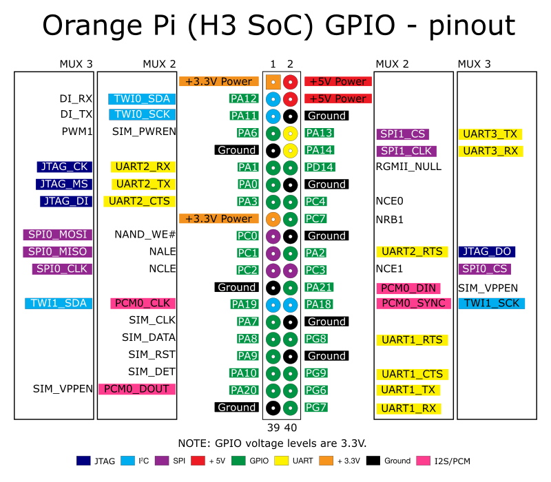
Addionally pins PG6 and PG7 were used for some early testing for the related Weather Station project.
The Enclosure
I’m really happy with this enclosure, while fairly small at 180x105x77mm; there’s enough room to get all the functionality I want inside fairly comfortably. The AU $20 spent got me the aluminium enclosure with heavy duty cover, waterproof front lens and rear panel with waterproof cable connectors, an additional hole will be requied for the PoE connector soon.
The First Radio
I’ve been using an RTL radio on this Pi for some time now, infact it was the running the first ADS-B monitoring centre here at VK2WAY before the project that made it operational 24x7. Both SoapySDR and rtl_tcp are used here for providing network access to the RTL SDR when needed. This radio is currently a Nooelec RTL SDR, Low Noise Amplifier and DC Block, powered via USB because I didn’t think ahead and get the SDR with bias-T power to the antenna.
When the LNA, DC Block and SDR are combined back-to-back and connected to the USB connector of the Orange Pi, it becomes quite long and obviously not going to fit inside of the enclosure.
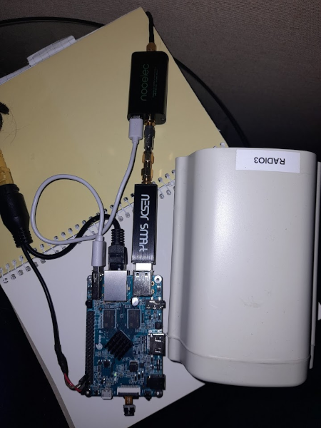
This isn’t a bad thing, because of heat and RF noise we’re going to keep the RTL SDR, LNA and other radio equipment outside of this main enclosure and run USB to it. This again keeps the project modular too, allowing the SDR and antennas to be disconnected from this compute device and used with any other laptop or device needed.
Getting the Power
To reduce the overhead of what is required in the device itself, I decided to use an existing 5V 3A power supply and a “power over ethernet converter” that accepts any DC input and delivers it on the output, rather than a conventional standard PoE Supply. This may be revised in the future depending on the cable length that ends up being between the injector and extractor, but for now testing has started using this method.
The converters can be picked up very cheaply on AliExpress at 12V Power Over Ethernet Passive POE including waterproofing and mounting hardware.
On the splitter end of the adapter I removed the DC jack and replaced it with two duPont female header pins to directly utilise the 5V and GND pins provided on the Pi for external power. Neatly heatshrink the individual connectors, be sure sure to add a litter larger heatshrink first to bring over to top for a profesional finish!
More testing is required on exactly how long and what cable will be needed to ensure adequate power gets along whatever the final run for this device is, so keep in mind that it will unlikely remain at this 5V, though we’re going to try!
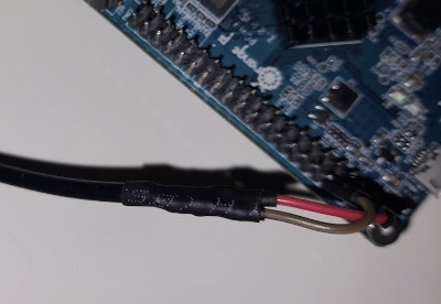
I did a quick test of the cable with a multimeter and everything looked fine, now to trust the documentation that the 5V and GND pins ARE the ones that they say they are on the Orange Pi, connect them up and test it out. It blinks into action and starts boot!